EMITEC Urea Dosing Pump Interfaces
4.1 Mechanical interface
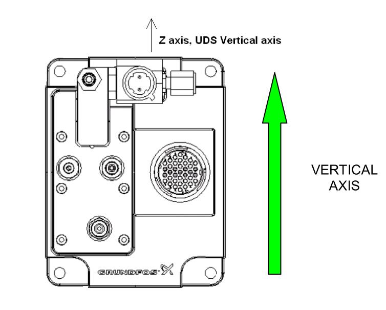
The UDA is designed to be flanged over a vertical bracket. (Dosing unit location in application see § 2)
For proper priming operation it is important that the UDA vertical axis Z is pointing top vertical.
In case of any doubt or other installation orientation, please take contact with Emitec.
CAUTION: FOR PROPER OPERATION, IT IS THE MOST IMPORTANT THAT THE UDA IS MOUNTED IN RESPECT TO ITS VERTICAL AXIS (THE SOLENOID VALVE MUST BE ON THE TOP)
THE UDA MUST BE DISCONNECTED BEFORE ANY WELDING ON THE VEHICLE
Note that the system once primed can run when the vehicle itself is having angularity +/- 45 degrees worst case.
The UDA is a high precision item and it is from the most importance that the receiving bracket is flat within 0.2mm in order
to avoid UDA case deformation.
We specify to bold the UDA over a flat bracket by the mean of 4 M8 screws torqued at 2.2 daN.m.
Flanged screws or nuts or screws with thick washer are needed to bolt the UDA over its mounting bracket.
CAUTION: IT IS STRONGLY RECOMMENDED THAT THE UDA HAS TO BE GROUNDED TO CHASSIS FOR PROPER EMC PROTECTION. TO DO SO THE ELECTRICAL CONNECTION MUST BE DONE WITH PROPER SCREWS OR WASHER THAT INSURE A PROPER GROUNDING.
The UDA can be either front mounted or rear mounted; the bracket flange should follow the shape below:

4.2 Hydraulic interface
The UDA ports are noted as follow:

Note *: Those port connection M12x1.5 as per ISO 4039-1 are reduced to 9 mm deepness, contact Emitec for
more information.
Emitec specify using the quick fitting and supplier specified mounting torque, over torque has to be avoided. We specify Poka Yoke on connection to avoid any mix of pipe during servicing operation.
Emitec recommends quick fitting type SAE as per J2044. Other connection types have to be discussed and agreed during development phase. Connectors type agreed with customer are specified into the SCD.
For proper UDA operation and best performances we specify to pipe the UDA according to the following table.
CAUTION: INTRODUCTION OF ANY UREA (EVEN IN A VERY SMALL AMOUNT) IN FORM OF LIQUID OR CRYSTALS INTO THE AIR SUPPLY PORT A IS CREATING PERMANENT DAMAGE TO THE UDA.
ALL AIR PIPING WHICH HAVE BEEN POLLUTED WITH UREA HAVE TO BE REPLACED BY NEW COMPONENTS.
QUICK FITTING NIPPLE MUST NOT BE EXCHANGED FROM ONE PORT TO ANOTHER
DURING HANDLING AND STORAGE, ALL PORTS HAVE TO BE PROTECTED (E.G. USING DUST CAPS)

On request, Emitec can supply some proposals regarding quick fitting connectors creating Poka yoke on piped connection to the UDA.
Applications deviating from these requirements need to be validated by Emitec. All listed performances were done with above indicated lines. Any changes will need to be tested in order define potential influence. Emitec won’t take any responsibility in case of changes without feedback from customer.
4.3 Electrical interface
Mating interfaces
Customer connector type, pin layout and poke yoke are defined in the Source Control Drawing (SCD)
Air unit solenoid valve connection
APD/DIN 72585 code 3 (green, RAL 6029) 1-2, 2 pins
The UDA Air Unit solenoid coil is supplied with the solenoid valve connector. The supply signal is coming from the UDA main connector through the application harness.
The application harness has to connect the main connector pins # 35 & 36 to the 2 pins solenoid valve connector.
CAUTION : DO NOT SUPPLY 24 VDC TO THE AIR UNIT VIA THE APD/DIN 72585 CODE 3 1-2, 2 PINS. THE DOSING UNIT IS SUPPLYING A PWM SIGNAL TO THE AIR UNIT SOLENOID VALVE COIL VIA APPLICATION HARNESS.
HIGHER VOLTAGE IS DAMAGING THE SOLENOID VALVE COIL
CAUTION : DO NOT HANDLE THE UDA BY AIR UNIT
4.4 Communication interface
Can Communication
The UDA communication protocol is fully compatible with full SAE J1939 CAN standard.