Detailed Explanation of the Hardware/Software Architecture and Working Principle of Automotive ECUs
1. Introduction to ECUs
An ECU (Electronic Control Unit) is an embedded system that controls one or more electrical systems in a vehicle. Modern vehicles incorporate numerous ECUs, which may include some or all of the following: Engine Control Module (ECM), Powertrain Control Module (PCM), Transmission Control Module (TCM), Brake Control Module (BCM or EBCM), Central Control Module (CCM), Central Timing Module (CTM), Generic Electronic Module (GEM), Body Control Module (BCM), and Suspension Control Module (SCM).
Each ECU typically contains a dedicated microprocessor that runs its own software or firmware and requires power and data connections to operate. ECUs utilize closed-loop control. They can be reprogrammed by updating their software or replacing their microchips.
ECUs receive inputs from various parts of the vehicle according to their function. For example:
A Door Lock ECU receives input when a passenger presses the lock/unlock button on a door or wireless key fob.
An Airbag ECU receives input from crash sensors and sensors detecting occupant presence in specific seats.
An Automatic Emergency Braking (AEB) ECU receives input from forward-facing radar sensors detecting when the vehicle is approaching an obstacle too rapidly.
The ECU then communicates with actuators to perform actions based on the inputs. For instance:
The Door Lock ECU activates an actuator to lock or unlock the corresponding door.
The Airbag ECU determines which airbags to deploy based on occupant position and signals the actuators to deploy them.
The AEB ECU engages the brakes to prevent a collision.
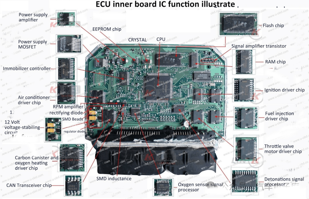
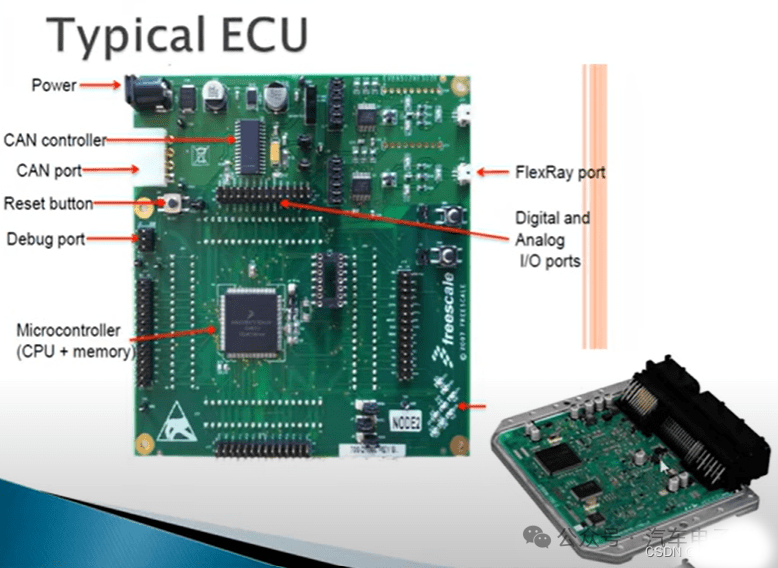
2. ECU Components
Microcontroller (Core component)
Memory (e.g., SRAM, EEPROM, Flash – for storing different software components)
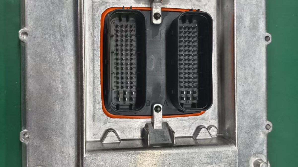
Inputs (Power, Digital Inputs, Analog Inputs)
Outputs (Actuators, Drivers, H-Bridge Drivers, Servo Motors, Logic Outputs)
Communication Links (CAN, LIN)
Embedded Software (Bootloader; Metadata for ECU and software identification, version management, checksums; Functional software routines; Configuration data)
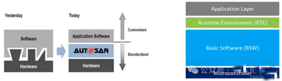
3. ECU Software
ECU software is divided into Application Layer Software and Base Layer Software. These layers are connected via the RTE (Runtime Environment).
4. ECU Working Principle
Working Principle: The input circuitry receives signals from sensors and other devices. It filters, processes, and amplifies these signals, converting them to standardized input voltage levels. Signals sent from sensors to the ECU input circuitry can be either analog or digital. An A/D (Analog-to-Digital) converter within the input circuitry converts analog signals into digital signals for the microcontroller, The microcontroller performs computational processing on these pre-processed signals and sends the resulting data to the output circuitry.