
Working Principle of Electronically Controlled High-Pressure Common Rail Injector Solenoid Valve
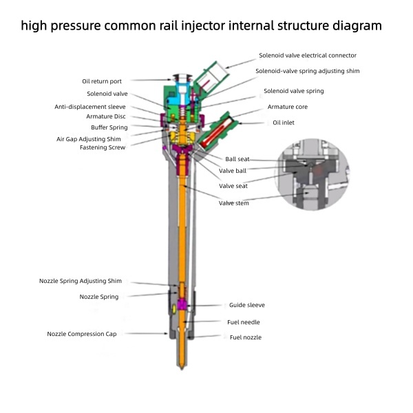
Working Principle of Electronically Controlled High-Pressure Common Rail Injector Solenoid Valve
The high pressure common rail injector is the core executive component of diesel engine fuel supply system, and its opening and closing actions are fully controlled by the built-in solenoid valve. When the injector solenoid valve is not actuated, the ball seat presses the valve ball against the oil drain hole of the valve seat to seal the drain hole, blocking high-pressure common rail fuel oil from flowing into the upper chamber of the valve seat.
High common rail pressure is maintained inside the nozzle chamber. The combined force formed by the common rail hydraulic pressure acting on the end face of the control plunger and the nozzle spring exceeds the opening force generated by high-pressure fuel on the conical surface of the needle valve. As a result, the needle valve is forced to retract into the valve seat, isolating and sealing the high-pressure fuel passage from the combustion chamber, so the needle valve stays fully closed.
1.How High Pressure Common Rail Injector Closes the Needle Valve
When the injector solenoid valve is not actuated, the ball seat presses the valve ball against the oil drain hole of the valve seat to seal the drain hole, blocking high-pressure common rail fuel oil from flowing into the upper chamber of the valve seat. High common rail pressure is maintained inside the nozzle chamber. The combined force formed by the common rail hydraulic pressure acting on the end face of the control plunger and the nozzle spring exceeds the opening force generated by high-pressure fuel on the conical surface of the needle valve. As a result, the needle valve is forced to retract into the valve seat, isolating and sealing the high-pressure fuel passage from the combustion chamber, so the needle valve stays fully closed.
2: Opening Logic of High Pressure Common Rail Injector Solenoid Valve
Once the solenoid valve receives an electrical signal and is actuated, the armature plate and ball seat move upward to lift the valve ball, opening the oil drain hole simultaneously. This action causes an immediate pressure drop inside the control chamber, which further reduces the hydraulic pressure acting on the control plunger. When the combined downward force of the plunger pressure and nozzle spring falls below the upward hydraulic force on the pressure-bearing conical surface of the injector needle valve (the fuel pressure in the nozzle chamber remains at full common rail high pressure), the needle valve lifts open. High-pressure fuel then sprays through the nozzle orifices into the combustion chamber.
This indirect actuation design for the needle valve relies on a hydraulic force amplification system. A solenoid valve cannot generate sufficient instantaneous force to open the needle valve directly at the required response speed. Instead, the valve opening process is realized indirectly: the solenoid valve opens the oil drain port to depressurize the control chamber, which in turn lifts the needle valve for fuel injection.
3: Reset Process of High Pressure Common Rail Injector After Fuel Injection
As soon as power to the solenoid valve is cut off, the solenoid valve spring pushes the armature core and ball seat downward to reseat the valve ball and close the oil drain hole. With the drain hole sealed, high-pressure fuel flows into the valve control chamber via the oil inlet to rebuild full rail pressure. The rail pressure exerts a downward thrust on the plunger end face; together with the preload force of the nozzle spring, the total downward force becomes greater than the upward hydraulic pressure from high-pressure fuel on the needle valve’s conical surface, forcing the injector needle valve to close and terminate fuel injection.
4: Fuel Leakage & Oil Return Design of High Pressure Common Rail Injector
Due to the extremely high working fuel pressure, minor fuel leakage inevitably occurs at the clearance fit between the needle valve and injector housing. All leaked fuel flows through the oil return channel and exits the injector via the oil return port for circulation recovery.
high pressure common rail injector internal structure diagram
Please contact us for more fuel injectors
See more products: Products Archive – Sukorun